A GPS receiver determines its position using a process called trilateration. This is simplest to understand if we first examine a simple case (Figure 1). Pretend that GPS-like signals are being transmitted from radio towers in Fresno, Los Angeles, and Las Vegas. Let's say you can decode the signals so that you know how far away you are from each transmission tower (R1, R2, and R3). Use the known distance as the radius for drawing a circle around each tower. If you only have the signals for Las Vegas and Los Angeles, then you could be at one of two intersection points for those two circles. But if you add the "satellite" from Fresno, you can figure out where you are exactly because there is only one intersection point for all three circles. Figure 2 shows you the real-world GPS version of trilateration. Instead of circles, think of each GPS satellite signal defining a sphere. The GPS receiver on the Earth is located at the intersection of those spheres.
Now you need to ask yourself two big questions:
How do you know the radii of those spheres?
How do you know where the satellites were when they sent their signals?
 from three transmission towers in Los Angeles, Fresno, and Las Vegas, she can calculate her location.")
 is the intersection of three spheres (in red). A fourth satellite (shown by the yellow line) gives you time.")
The GPS signal was designed especially to answer those two questions. Each GPS satellite sends out a unique code. That code is a series of ones and zeros (Figure 3). The GPS receiver in your car or phone has a copy of each satellite code. When GPS signals come in, the receiver electronics has to figure out which satellites sent them. It carefully compares the received GPS signals with the codes for all the satellites it knows about. Once the receiver has identified each satellite, it shifts the codes to line up the received code with the code inside its memory. The shift represents the amount of time the satellite code took to reach the receiver. We use this time shift to calculate how far away the satellite was when it sent the signal. Say each tic mark on the code represents 1 millisecond. If the receiver has to shift the codes 70 tic marks, the signal took 70 milliseconds to travel from the satellite to the Earth. To convert that to distance, we multiply by the speed of light (~3x10⁸m/s). That gives you roughly 21,000,000 meters.


Now the receiver knows how far away each satellite was when it sent the signal. But there is still more work to be done. Remember that we said every satellite has its own clock? That means the radius of each of those spheres in Figure 2 will be slightly off, depending on whether that satellite clock is running fast or slow. This is not a trivial problem because satellite clock variability can produce errors as great as 150 km! (See this figure for some typical clock corrections). This problem is solved by the control segment we talked about on the Satellites, Controllers, Users page. The Master Control station synchronizes all the satellite clocks and transmits their corrections to users.
Finally, we need to know where the satellite was when it sent the signal. GPS satellites are traveling at speeds of ~4 km/sec, so it is important to know the location of the coordinates extremely well. Fortunately, the Master Control center is able to provide that information in real-time with a precision of a few meters. The last thing the GPS receiver needs to do is synchronize its clock with the GPS constellation. It uses measurements from a fourth satellite to do that.
Last modified: 2019-12-26 16:24:58 America/Denver

Please send comments and corrections to education unavco.org.
Copyright © 2012 - 2026 UNAVCO and the GPS Reflections Research Group.
All Rights Reserved.

 Spotlight Map
 GNSS Videos
 Funding and Acknowledgements
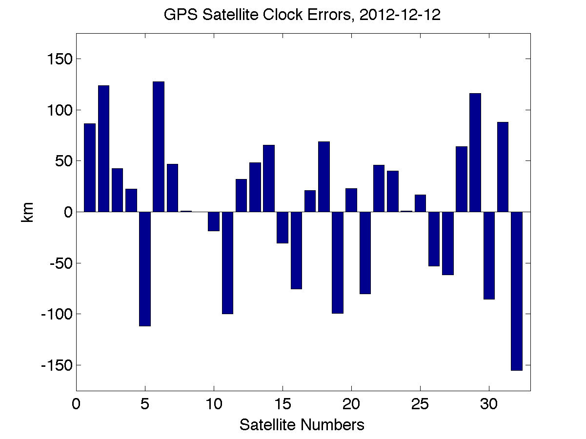